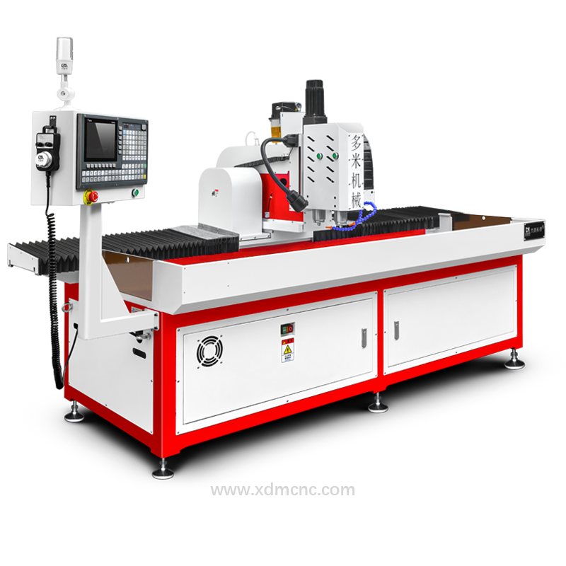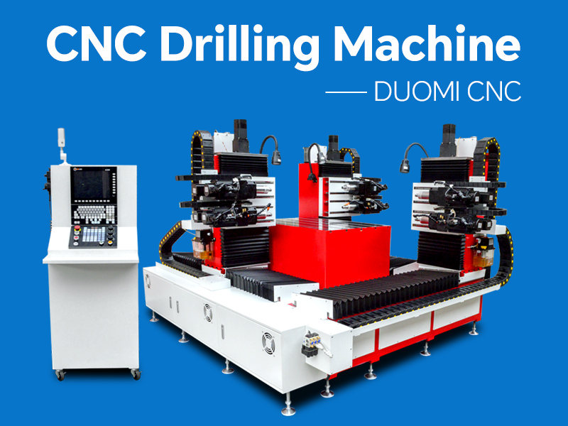
In modern manufacturing, CNC drilling machines play a critical role in achieving high efficiency, precision, and consistency across industries such as metal fabrication, automotive components, aerospace, and furniture production. Among the most important parameters that directly affect machining performance are feed rate (F) and peck drilling depth (Q). Proper optimization of these parameters can significantly improve productivity, extend tool life, and ensure superior hole quality—especially when working with challenging materials such as stainless steel, titanium, and mold steel.
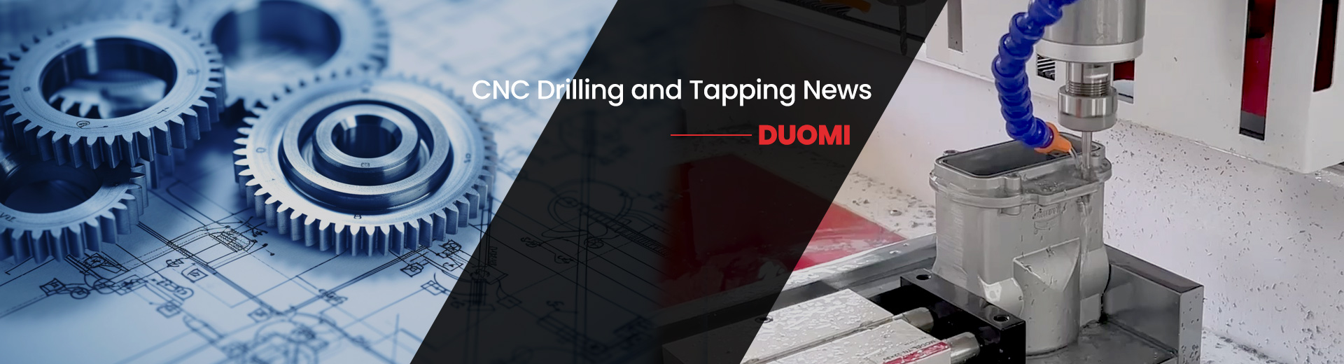
Optimizing Feed Rate and Peck Drilling Depth in CNC Drilling Machines
1. Understanding Feed Rate (F) in CNC Drilling
Feed rate refers to the speed at which the cutting tool advances into the workpiece. It is typically measured in millimeters per minute (mm/min). In CNC programming, the feed rate is defined by the F code, such as:
G01 X100 Y50 F200
The feed rate directly influences cutting efficiency, surface finish, heat generation, and tool wear.
Key Factors Affecting Feed Rate Optimization
1.1 Material Properties
Different materials require different feed rates:
Soft materials (aluminum, plastic): Higher feed rates can be used to improve efficiency.
Hard materials (stainless steel, titanium): Lower feed rates are necessary to prevent tool damage and excessive heat.
1.2 Tool Diameter and Geometry
Larger tools can typically handle higher feed rates.
Smaller or micro-drills require slower feed to prevent breakage.
1.3 Spindle Speed (S) Coordination
Feed rate must be balanced with spindle speed. A mismatch can cause:
Tool wear
Poor surface finish
Tool breakage
A common guideline is to maintain a proper chip load, ensuring that each cutting edge removes an optimal amount of material.
2. Understanding Peck Drilling Depth (Q)
Peck drilling is a technique used to improve chip evacuation and reduce tool stress, especially in deep hole drilling. The Q parameter defines the incremental depth per drilling cycle.
Example:
G83 Z-20 Q5 R2 F100
In this case, the tool drills 5 mm at a time before retracting to clear chips.
Why Peck Drilling is Important
Prevents chip accumulation
Reduces heat buildup
Extends tool life
Improves hole accuracy
3. How to Optimize Peck Drilling Depth
3.1 Material-Based Adjustment
Stainless Steel: Smaller Q values (e.g., 1–3 mm) to ensure effective chip breaking.
Titanium: Even smaller peck depths due to low thermal conductivity and high cutting resistance.
Aluminum: Larger Q values can be used due to better chip flow.
3.2 Hole Depth Consideration
Shallow holes: Peck drilling may not be necessary.
Deep holes: Smaller Q values are recommended to maintain chip evacuation efficiency.
3.3 Tool Type and Coating
High-performance carbide drills can tolerate larger peck depths.
Coated tools (TiN, TiAlN) reduce friction and heat, allowing better performance at higher parameters.
4. Balancing Feed Rate and Peck Depth
The relationship between feed rate and peck depth is crucial. These two parameters must be optimized together to achieve stable and efficient machining.
Key Principles:
Higher feed rate + smaller peck depth → Suitable for tough materials
Lower feed rate + larger peck depth → Suitable for soft materials
Balanced combination → Best for general applications
Incorrect parameter settings may lead to:
Tool breakage
Poor hole quality
Excessive vibration
Reduced tool life
5. Practical Optimization Strategies
5.1 Use Trial Cutting
Before mass production, perform test drilling to determine the optimal F and Q values.
5.2 Monitor Cutting Conditions
Pay attention to:
Chip shape (ideal chips are short and uniform)
Cutting sound
Surface finish
5.3 Adjust Parameters Dynamically
Advanced CNC systems allow adaptive machining:
Adjust feed rate based on load
Modify peck depth for different layers of material
5.4 Utilize High-Pressure Coolant
Proper cooling:
Reduces heat
Improves chip evacuation
Allows higher feed rates and deeper peck cycles
6. Industry Application Example
In applications such as stainless steel square tube drilling, optimizing feed rate and peck depth is critical:
Feed rate is carefully controlled to prevent deformation.
Peck drilling ensures chips are removed efficiently from inside the tube.
Typical parameters might include:
Feed rate: Moderate to low
Peck depth: Small increments (1–3 mm)
High-speed spindle with coolant assistance
This combination ensures both productivity and precision in mass production environments.
Optimizing feed rate and peck drilling depth in CNC drilling machines is essential for achieving high-quality machining results. A well-balanced combination of these parameters can significantly improve efficiency, reduce tool wear, and enhance overall production stability.
Manufacturers should consider material type, tool characteristics, and machining requirements when selecting parameters. Through careful testing, monitoring, and adjustment, CNC operators can achieve optimal performance and maximize the return on their machining systems.
For industrial CNC drilling applications, continuous parameter optimization is not just a technical requirement—it is a key factor in maintaining competitiveness in modern manufacturing.