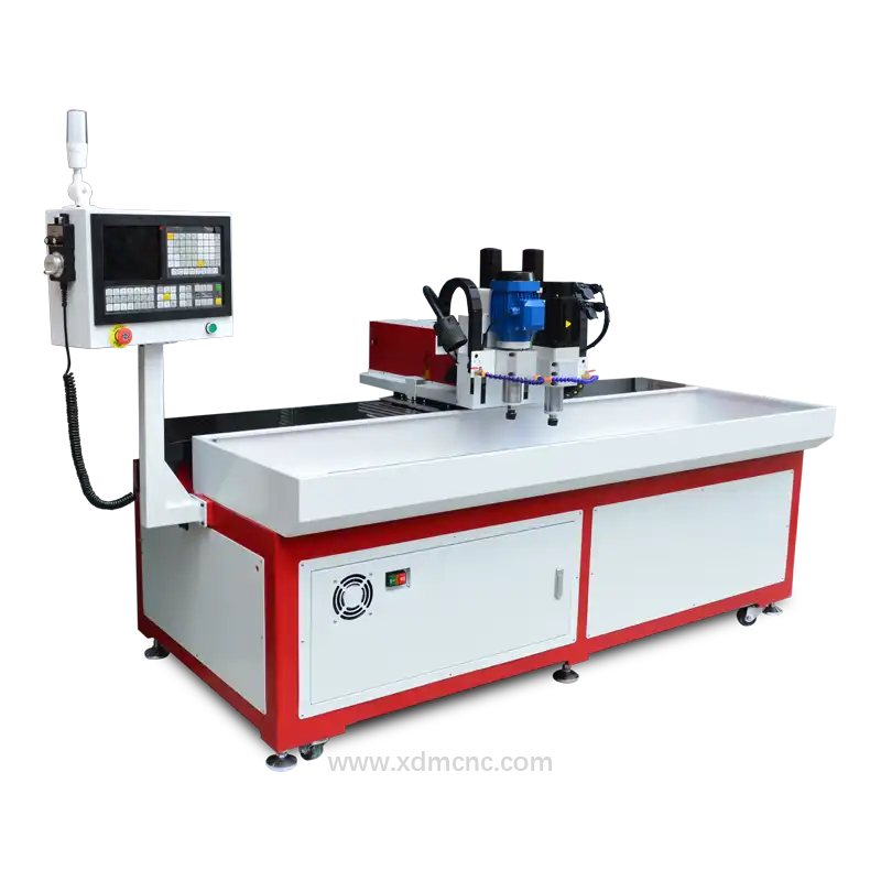
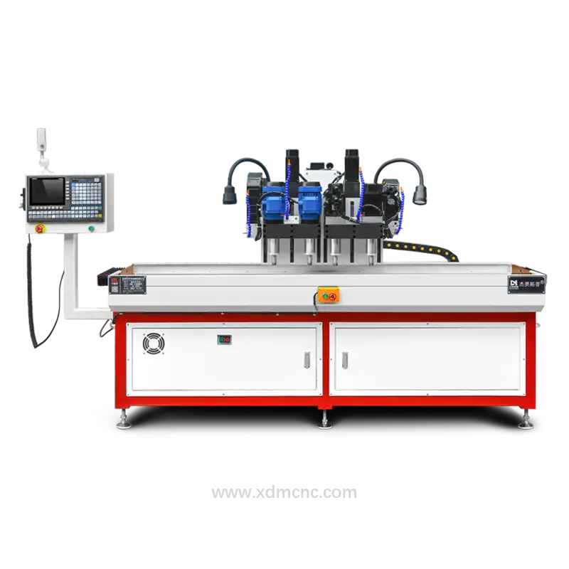
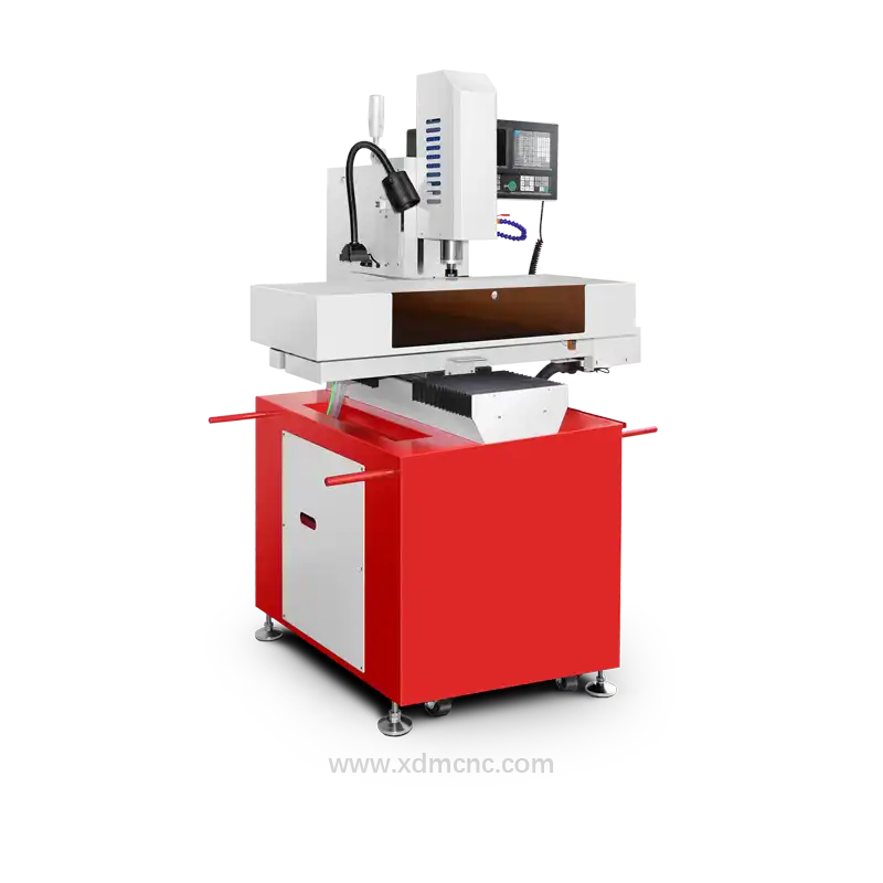
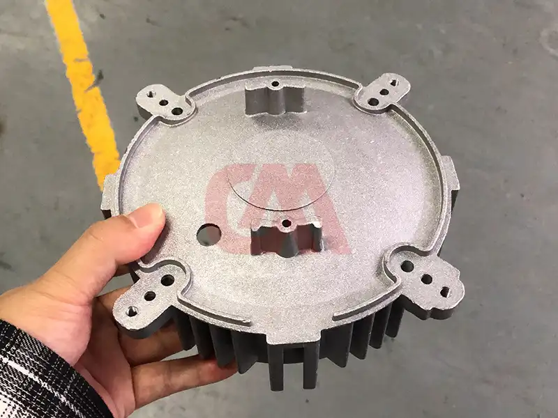
The process of drilling and tapping in die-cast aluminum involves creating precision holes and cutting internal threads on aluminum alloy components. Die-cast aluminum alloys—such as A380, ADC12, and A360—are widely specified across automotive housings, 5G telecom enclosures, and industrial motor casings due to their high strength-to-weight ratio and casting flexibility. However, high silicon content in these castings presents challenges such as tool wear, thermal expansion, and chip sticking.
To achieve consistent thread quality and tight positional tolerances, dedicated CNC drilling and tapping machines equipped with high-speed spindles and rigid tapping capabilities are essential.
Key Process Parameters & Technical Considerations
1. Drill Bit Selection & Geometry
While aluminum is relatively soft, silicon inclusions in die castings are abrasive. Standard high-speed steel (HSS) drills degrade quickly under mass production conditions. * Material Selection: Solid carbide or micro-grain tungsten carbide tools with Diamond-Like Carbon (DLC) or TiAlN coatings are recommended. * Geometry: A 135° or 140° split point angle with a 30° helix angle ensures self-centering, minimizes burr formation at hole exit, and provides efficient chip evacuation.
2. Tapping Tooling & Threading Techniques
Selecting the right tap depends on material ductility, hole depth, and thread specification (e.g., ISO 965 6H thread fit). * Spiral Flute Taps: Ideal for blind holes as they pull chips up and out of the cavity, preventing chip packing. * Straight Flute Taps: Suitable for through-holes or short thread depth applications. * Forming Taps (Thread Rolling): Preferred for low-silicon, ductile aluminum alloys to eliminate chip generation altogether, producing stronger thread grains without metal removal.
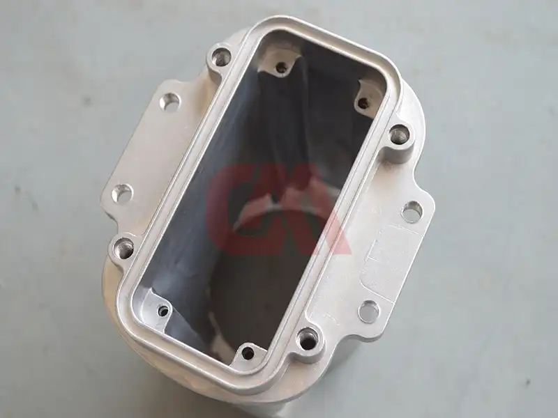
3. Machining Speeds, Feeds, and Coolant Application
Proper thermal control prevents aluminum built-up edge (BUE) on tool cutting lips.
| Process Parameter | Recommended Value / Setting |
|---|---|
| Drilling Cutting Speed ($V_c$) | 150 – 350 m/min |
| Tapping Speed ($V_c$) | 15 – 35 m/min |
| Spindle Speed Range | 8,000 – 15,000 RPM |
| Coolant Pressure | High-pressure (20–70 bar) or MQL (Minimum Quantity Lubrication) |
| Coolant Type | Water-soluble synthetic emulsion with extreme-pressure (EP) additives |
4. Hole Tolerances and Quality Control
- Dimensional Accuracy: Modern CNC tapping systems maintain hole positional accuracy within ±0.01 mm to ±0.02 mm, compliant with ISO 2768-m standards.
- Rigid Tapping Synchronization: Electronic synchronization between spindle rotation and feed axis guarantees accurate thread pitch and eliminates tap breakage.
5. Surface Treatment & Post-Processing
After machining, residual burrs must be removed through thermal or mechanical deburring. Surface finishes such as anodizing, chromate conversion coating, or powder coating enhance corrosion resistance and prep the machined features for final assembly.
Advanced Multi-Spindle Solutions for High-Volume Production
For mass production of complex die-cast parts like automotive engine covers and gearbox housings, multi-spindle CNC drilling and tapping machines allow simultaneous machining of multiple hole patterns, reducing total cycle times by up to 60%.
Need High-Efficiency CNC Drilling & Tapping Machinery?
Consult with our senior application engineers to get a custom cycle time simulation and tailored machine proposal within 24 hours.